Pressure Protection
Figure 1:AI Generated Image of a Reactor
What would be the consequences if the reactor in the image above were to over-pressurize?
The reactor could explode, causing damage to the plant and surrounding area
The reactor could release hazardous chemicals into the environment
The reactor could release hazardous chemicals into the plant, causing harm to personnel
Explosion approximate consequences:
#Potential energy from exploding reactor
ReactorVolume = 50 #m^3 (13,200 gallons)
VoidFraction = 0.67 #67% void fraction
Contents = 'Acetone'
BurstPressure = 10 #bar
ContentMass = ReactorVolume * (1 - VoidFraction) * 785 #kg/m^3, Acetone density estimate
CombustionHeat = 30.819e6 #J/kg: 1790 kJ/mol, molecular weight 58.08 g/mol
#Energy from bursting reactor scales with burst pressure and void volume:
BurstEnergy = BurstPressure * ReactorVolume * 1e5/(1.4-1)*(1-1/BurstPressure)**((1.4-1)/1.4) #Joules
print('BurstEnergy, MJ: ', BurstEnergy/1e6)
CombustionEnergy = ContentMass * CombustionHeat #Joules
print(f'CombustionEnergy, MJ: {CombustionEnergy/1e6:.2f}')
#energy to power 1 homes for a year
EnergyPerYear = 100e6 #J
print(f'Energy could power {(CombustionEnergy+BurstEnergy)/EnergyPerYear:.2f} homes for a year')BurstEnergy, MJ: 121.29319730813798
CombustionEnergy, MJ: 399183.10
Energy could power 3993.04 homes for a year
What steps could be taken to prevent the reactor from over-pressurizing?
Code requirements (RAGAGEP) for pressure relief devices are found in Boiler and Pressure Vessel Code (ASME), Section VIII, Division 1, API 520, and others.
Many vessels are required to have pressure relief protection including
Pressure vessels
Blocked-in sections of liquid-filled piping
Heat exchangers
Storage tanks
What are some ways that elevated pressures could occur?
Types of Pressure Protection Devices
Spring Operated Relief Valves
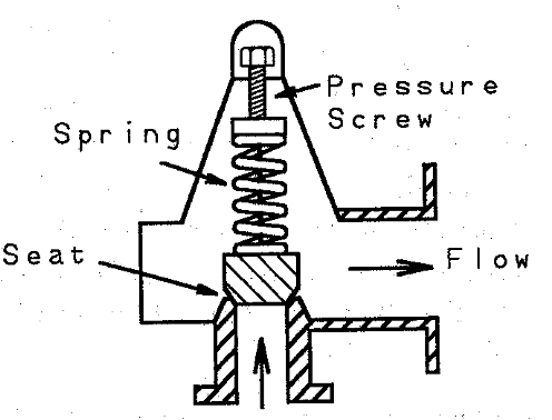
Figure 2:Drawing of the internal components of a spring operated relief valve.
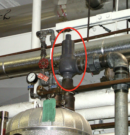
Figure 3:Image of a spring operated relief valve installed.
Some components of spring operated relief valves include:
Spring - the spring is compressed by the process pressure
Valve plug - the plug is lifted off the seat when the spring force is overcome by the process pressure
Nozzle - the nozzle directs the flow of the relieving fluid
Seat - the plug seals against the seat to prevent flow
Comments on spring operated relief valves:
very common
versatile: can be used for gas or liquid
reliable
susceptible to chatter
relieving pressure affected by temperature, back pressure, and accumulation
flow decreases with increasing back pressure
Balanced Bellows Relief Valves
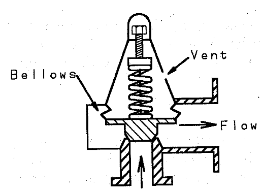
Figure 4:Drawing of the internal components of a balanced bellows relief valve.
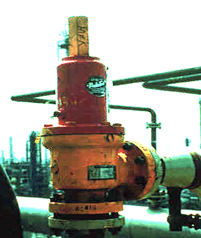
Figure 5:Image of a balanced bellows relief valve installed.
Some components of balanced bellows relief valves include:
Bellows - the bellows is a flexible diaphragm that is used to sense the process pressure
Valve plug - the plug is lifted off the seat when the bellows force is overcome by the process pressure
Nozzle - the nozzle directs the flow of the relieving fluid
Seat - the plug seals against the seat to prevent flow
Comments on balanced bellows relief valves:
similar to spring operated relief valves
relieving pressure is not affected by back pressure
flow decreases with increasing back pressure
spring is protected from the process fluid
flow through the valve can be impacted by back pressure
Pilot Operated Relief Valves
Some comments on pilot operated relief valves:
relieving pressure not affected by back pressure
can operate very close to set pressure
potential for back flow
o-ring seals limit some applications
Buckling Pin Relief Valves
Comments on buckling pin relief valves:
similar to a rupture disk
o-ring seals used and can limit some applications
less susceptible to corrosion (vs rupture disk)
can be operated closer to the set pressure (vs rupture disk)
can operate at very low set pressures
Rupture Disks

Figure 6:Drawing of the internal components of a rupture disk device.
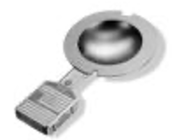
Figure 7:Image of a rupture disk.
Relief valves are often used in conjunction with rupture disks. Rupture disks are used to protect the relief valve from the process fluid. Rupture disks are often used in applications where the process fluid is corrosive, toxic, or would otherwise damage the relief valve.
Rupture disks are often made of a thin metal that is designed to rupture at a specific pressure. The rupture disk is installed in a holder that is designed to contain the disk fragments when the disk ruptures. Some other characteristics of rupture disks include:
often used in conjunction with relief valves
often used in applications where the process fluid is corrosive, toxic, or would otherwise damage the relief valve or small leaks over time would present risks to people and the environment
one-time use (does not close after relieving)
pieces of disk can be a hazard in the process
rapid response
there are multiple types:
reverse buckling
tension loaded
scored
pre-fragmented
composite
solid
knife blade
slotted
Some Definitions
| Term | Definition |
|---|---|
| Set Pressure | The pressure at which the relief device is set to open |
| Relief Pressure | The pressure at which the relief device actually opens |
| MAWP | Maximum Allowable Working Pressure, maximum gauge pressure permissible at the top of the vessel at the designated temperature |
| MAWT | Maximum Allowable Working Temperature, the maximum temperature at which the vessel is permitted to operate |
| MDMT | Minimum Design Metal Temperature, the lowest temperature at which the vessel is permitted to operate |
| Operating Pressure | The pressure at which the vessel is intended to operate; no more than 90% of the MAWP |
| Accumulation | The pressure increase over the MAWP that occurs when the relief device is operating; expressed as a percentage of the MAWP |
| Overpressure | The pressure increase over the set pressure that occurs when the relief device is operating; expressed as a percentage of the set pressure |
| Back Pressure | The pressure at the outlet of the relief device; composed of two components: pressure from downstream and pressure required for frictional losses |
| Blowdown | The difference between the set pressure and the relief reseating pressure |
| Maximum allowable accumulation pressure | Sum of the accumulation and the MAWP |
| Relieving pressure | The pressure at which the relief device is fully open and relieving: set pressure plus overpressure |
Code comments:
The maximum normal operating pressure can never exceed the MAWP, even momentarily. However, the actual pressure during the relieving process may exceed the MAWP.
Pressure tests (to verify strength) are often performed at 1.5 times the MAWP. Tests use water typically (gas tests would yield a much more violent failure if the vessel were to fail during the test).
For a single relief, the maximum set pressure is the MAWP.
During the relieving process, the overpressure cannot exceed the MAWP by more than the following percentages:
110% for vessels equipped with a single pressure relief device.
116% for vessels equipped with supplemental pressure relief devices.
121% for fire exposures.
For supplemental relief devices, the max. set pressure is 105% of the MAWP.
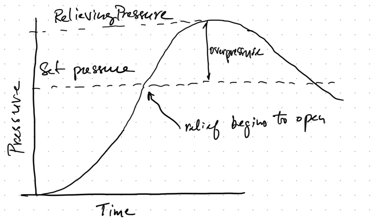
Figure 8:Plot of set pressure, relieving pressure, accumulation, and overpressure for a pressure relief device.
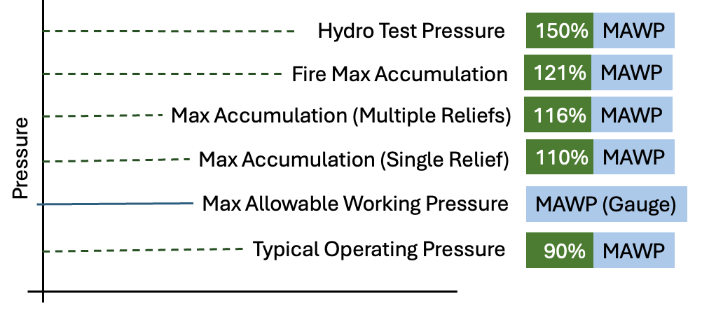
Figure 9:Plot of the various pressures associated with a pressure relief device.
Where and Why Pressure Protection Devices are Used
Vessels
All vessels, including reactors, storage tanks, heat exchangers, towers and drums.
Positive Displacement Pumps, Compressors, and Turbines
These devices can be blocked in by a closed valve, causing the pressure to rise. These processing pieces may have an internal relief valve.
Piping
Piping is not normally required or recommended to have pressure relief protection as piping can typically withstand pressures higher than the vessels they supply. However, there are some exceptions:
blocked-in sections of liquid-filled piping that may be heated or otherwise pressurized
heat traced piping
long lines (thermal expansion)
loading or transfer lines beyond the property line
lines with history of overpressure
lines that may be exposed to high pressures
per the hazards analysis
Examples of Where Pressure Protection Devices are Used
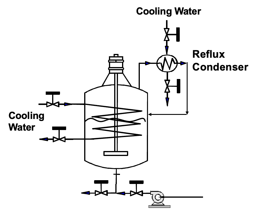
Figure 10:Example drawing of a reactor with cooling and reflux.
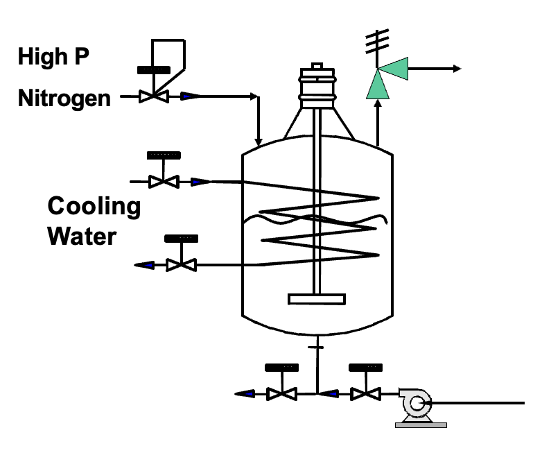
Figure 11:Image of a reactor with pressure relief device present on the reactor.

Figure 12:Process flow diagram of a polymerization process. *Source: Crowl and Louvar, Chemical Process Safety, 4th Edition, FIgure 9-8.
Relief Effluent Handling
Oft times, the relief effluent cannot simply be released to the atmosphere. The effluent may be toxic, flammable, or otherwise hazardous. The effluent may also be at a high temperature or pressure. Some options for handling the effluent include:
Flare
Vent to a scrubber
Vent to a thermal oxidizer
Vent to a condenser
Vent to a knock-out drum